"PiRTC" Extention
RTC with Supercapacitor backup and 64 bytes NVMEM

Description
The "PiRTC" Extention is an RTC (PCF85363) with Super-capacitor power backup and 64 bytes of non-volatile RAM (provided by the RTC chip).
The Board uses the 26 pins version of the common extention connector found on many SBC with a form factor close to the original Raspberry Pi, often compatible with the pinout of the 40 pin connector.
The board comes fully assembled and tested.
Where to buy
- Contact us by email before (sales *at* techno-innov.fr) to get a quotation which will include shipping costs and reduction for direct order.
License
By purchasing one of our products, you become the owner .Therefore, you have some rights and obligations according to the following licences :
- Documentation : Creative Commons CC BY-SA-NC 4.0
- Hardware : The PiRTC hardware and schematics are under Creative Commons CC BY-SA-NC 4.0 License. You can produce your own original or modified version of the PiRTC, and use it however you like, but not sell them, even without profit.
- Software : All the software examples created by Techno-Innov for the PiRTC are under GPLv3 License.
- Note that most of the software you will use with this Hat has not been written by us and is covered by other licenses. Refer to each software for more information.
Waranties
Because it is impossible for Techno-Innov to know the purposes for which you acquired this product or the uses to which you will put this product, you assume full responibility for the selection of the product and for its installation and use.
While every reasonnable effort has been made to insure that you will receive a product that you can use and enjoy, Techno-Innov does not warrant that the functions of the product will meet your requirements or that the operation of the product will be uninterruped or error-free. Techno-Innov is not responsible for problems caused by the interaction of the product with any other software or hardware.
Hardware (Mechanical)
Dimensions
-
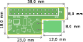
Fig 1 - Mechanical

Figure 1 gives the different dimensions and the position of the main elements of the PiRTC board.
Connectors

The PIRTC has one 2.54mm pitch headers numbered P1 (26 pins Pi connector).
Detailed description of the signals found on each connector pin follow.
- P1 : 26 pins, 2.54mm pitch header. Used to connect to PI expansion header.
P1 Connector

P1 connector is a standard 2.54mm (0.1 inch) pitch header, with 2 row of 13 pins.
P1 connector is used to connect to the PI expansion header.
| P1 connector | ||
|---|---|---|
| Pin # | Description | Pi signal |
| 1 | +3.3V from Pi | +3.3V |
| 2 | +5V from Pi | +5V |
| 3 | SDA : Bidirectional Serial Data for I²C bus 1 | I2C1 SDA |
| 4 | +5V from Pi | +5V |
| 5 | SCL : Clock for I²C bus 1 | I2C1 SCL |
| 6 | GND : Ground | GND |
| 7 | RTC GPIO | GPIO |
| 8 | ||
| 9 | GND : Ground | GND |
| 10 to 13 | ||
| 14 | GND : Ground | GND |
| 15 to 19 | -- | -- |
| 20 | GND : Ground | GND |
| 21 to 24 | -- | -- |
| 25 | GND : Ground | GND |
| 26 | -- | -- |
Electronic components

The PiRTC Board has been created using KiCad EDA software suite for the creation of the schematics and printed circuit boards.
See below for the full schematics. The sources for the schematics are available for download here.
Main Components Description
- U1 : NXP PCF85363 RTC Clock.
- U2 : TI LP2985 DC-DC step-down converter.
- SC1 : Bussmann 1 Farad supercapacitor.
I²C
The PiRTC uses the only I²C bus from the 26 pins Pi connector.
Bus 1 holds the PCF85363 RTC clock at address 0x51.
The following table shows all the possible I²C Addresses for the I²C components used on the PiRTC board.
| I²C Addresses | ||
|---|---|---|
| I²C Component | 7 bits I²C address | I²C Address + R / W bit |
| PCF85363 RTC Clock | 0x51 | 0xA2 / 0xA3 |
RTC Clock

The PiRTC uses a PCF85363 RTC with super-capacitor power backup.
The use of a Super-capacitor for power backup lowers the environmental footprint and remove the need to replace (and dispose of) the battery at the expense of a shorter time retention, which is between one and two months, but should be enough for most applications.
The Linux kernel has support for the PCF85363 RTC in the rtc-pcf85363 module.
CONFIG_RTC_DRV_PCF85363=m
After loading the rtc-pcf85363 module in the kernel, you must add the RTC to the list of devices on the I²C bus 1 :
echo pcf85363 0x51 > /sys/bus/i2c/devices/i2c-1/new_device
This is not necessary if the device tree already contains the corresponding information.
You can the access the RTC with the hwclock command (from the util-linux package on Debian based GNU/Linux distributions) as one of the /dev/rtcN (replace 'N' with the appropriate RTC number).
RTC Clock - NVMem
The RTC clock selected also holds 64 bytes of RAM available to the user to store data as long as the RTC chip is powered (which includes the super-capacitor backup power).
To get access to this memory you will need to activate the following conigurations in your kernel :
CONFIG_RTC_NVMEM=y
CONFIG_NVMEM=y
CONFIG_NVMEM_SYSFS=y
When booted with a kernel with NVMEM support activated (with the PCF85363 RTC support, either built-in or as module with module loaded) you will get access to the RAM bytes under /sys in the following file :
/sys/bus/nvmem/devices/pcf85363-0/nvmem
You can then use it as a regular file with a limited size of 64 bytes.
echo "NVMEM Test" > /sys/bus/nvmem/devices/pcf85363-0/nvmem
cat /sys/bus/nvmem/devices/pcf85363-0/nvmem
As it is a regular file, it can be accessed using regular file access mechanisms using any language (C, python, ...)
Software
RTC support
Kernel Modules (use modprobe to load them if they are not already loaded or included in the main kernel image) :
- RTC : rtc-pcf85363.ko
Check that the components are detected (example on RaspberryPi 4, your I2C bus number may have to be adapted to your board :
- root@raspberrypi:~# i2cdetect 1
- [...]
- 50: -- 51 -- -- -- -- -- -- -- -- -- -- -- -- -- --
- [...]
- echo pcf85363 0x51 > /sys/bus/i2c/devices/i2c-1/new_device
dtb information
Here is an example entry in the device tree for the PCF85363 RTC support.
&i2c0 {
   status = "okay";
   pcf85363: pcf85363@51 {
       compatible = "nxp,pcf85363";
       reg = <0x51>;
       status = "okay";
   };
};
Schematics, sources and PDF of documentation
- Current documentation (PDF subpart of what's on this page) here
- Schematics : here
- Board layout : here
- Sources for the schematics here
History
v0.1
This board revision has not been sold to public. First prototype version, produced on customer request.
v0.2
Actual version sold as of writting of this documentation. Move RTC GPIO Pin to P1 pin7 instead of P1 pin 8 (which is used as UART Tx on some boards).