GPIO-Demo Module
The GPIO-Demo module is intended to help prototyping with the LPC1224 microcontroller from NXP and has been designed as a base for the development of communication modules for the DomoTab project in order to validate mechanical and other common specifications of the modules.

Description
The GPIO-Demo module is a development board for the LPC1224 microcontroller from NXP, an ARM Cortex-M0 based microcontroller.
- USB powered
- two rows of 2.54mm (0.1 inch) connectors for use on rapid prototyping boards
- UEXT connector
- a USB to UART FTDI chip (FT230XS) to give you access to the first UART using a simple USB cable or to connect the board directly to your computer depending on the USB connector option you choose.
- an I²C EEPROM
- an I²C temperature sensor (TMP101 from Texas Instrument)
- Reset and ISP buttons
- a bicolor (green and red) user Led
The board comes either fully assembled and tested or as a CMS kit so you can test CMS assembly at home.
Where to buy
- Contact us by email before (sales *at* techno-innov.fr) to get a quotation which will include shipping costs and reduction for direct order.
License
- Documentation : Creative Commons CC BY-SA 4.0
- Hardware : The GPIO-Demo module hardware and schematics are under Creative Commons CC BY-SA 4.0 License. You can produce your own original or modified version of the PiSerialPower RPi Hat, and use it however you like, and sell them for profit.
- Software : All the software examples created by Techno-Innov for the GPIO-Demo module are under GPLv3 License.
Hardware (Mechanical)
Dimensions
-
Fig 1 - USB A board
-
Fig 2 - micro-USB board
-
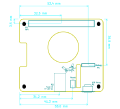
Fig 3 - Headers and UEXT connector

Figures 1, 2 and 3 give the different dimensions and the position of the main elements (Led, buttons, connectors) of the GPIO-Demo module.
Connectors
The Module has one USB connector numbered P6 (micro-USB female) or P7 (USB A male) depending on the board type, one UEXT connector (P1), four 2.54mm headers on the sides, and another 2.54mm header to give extra access to the UART. Refer to figure 4 for connectors position.
Detailed description of the signals found on each connector pin follow.
- P1 : 2x5 pins, 2.54mm pitch (0.1 inch) header : UEXT connector
- P2 : 10 pins, 2.54mm pitch header. Provides +5V from USB, ground, and 8 GPIO from port 0.
- P3 : 10 pins, 2.54mm pitch header. Provides 10 GPIO from port 0.
- P4 : 6 pins, 2.54mm pitch header. Provides 6 ADC inputs (can be used as GPIO).
- P5 : 2 pins, 2.54mm pitch header. Provides +3.3V and ground.
- P6 : USB microB female connector, available only on micro USB board type.
- P7 : USB A male connector, available only on USB A board type.
- P8 : 2 pins, 2.54mm pitch header. Provides access to Rx/Tx on USB to UART bridge.
P1 Connector
P2 Connector
P3 Connector
P4 Connector
P5 Connector
P6 Connector
P7 Connector
P8 Connector
| P8 connector | |||
|---|---|---|---|
| Pin # | Description | LPC1224 signal | LPC1224 Pin |
| 1 | +3.3V : 3.3V from USB to UART bridge or 3.3V input power | +3.3V | |
| 2 | GND : Ground | GND | GND pins |
Electronic components