GPIO-Demo Module
WORK IN PROGRESS
The GPIO-Demo module is intended to help prototyping with the LPC1224 microcontroller from NXP and has been designed as a base for the development of communication modules for the DomoTab project in order to validate mechanical and other common specifications of the modules.

Description
The GPIO-Demo module is a development board for the LPC1224 microcontroller from NXP, an ARM Cortex-M0 based microcontroller.
- USB powered
- two rows of 2.54mm (0.1 inch) connectors for use on rapid prototyping boards
- UEXT connector
- a USB to UART FTDI chip (FT230XS) to give you access to the first UART using a simple USB cable or to connect the board directly to your computer depending on the USB connector option you choose.
- an I²C EEPROM
- an I²C temperature sensor (TMP101 from Texas Instrument)
- Reset and ISP buttons
- a bicolor (green and red) user Led
The board comes either fully assembled and tested or as a CMS kit so you can test CMS assembly at home.
Where to buy
- Contact us by email before (sales *at* techno-innov.fr) to get a quotation which will include shipping costs and reduction for direct order.
License
- Documentation : Creative Commons CC BY-SA 4.0
- Hardware : The GPIO-Demo module hardware and schematics are under Creative Commons CC BY-SA 4.0 License. You can produce your own original or modified version of the PiSerialPower RPi Hat, and use it however you like, and sell them for profit.
- Software : All the software examples created by Techno-Innov for the GPIO-Demo module are under GPLv3 License.
Hardware (Mechanical)
Dimensions
-
Fig 1 - USB A board
-
Fig 2 - micro-USB board
-
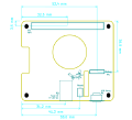
Fig 3 - Headers and UEXT connector

Figures 1, 2 and 3 give the different dimensions and the position of the main elements (Led, buttons, connectors) of the GPIO-Demo module.
Connectors
The Module has one USB connector numbered P6 (micro-USB female) or P7 (USB A male) depending on the board type, one UEXT connector (P1), four 2.54mm headers on the sides, and another 2.54mm header to give extra access to the UART. Refer to figure 4 for connectors position.
Detailed description of the signals found on each connector pin follow.
- P1 : 2x5 pins, 2.54mm pitch header : UEXT connector
- P2 : 10 pins, 2.54mm pitch header. Provides +5V from USB, ground, and 8 GPIO from port 0.
- P3 : 10 pins, 2.54mm pitch header. Provides 10 GPIO from port 0.
- P4 : 6 pins, 2.54mm pitch header. Provides 6 ADC inputs (can be used as GPIO).
- P5 : 2 pins, 2.54mm pitch header. Provides +3.3V and ground.
- P6 : USB microB female connector, available only on micro USB board type.
- P7 : USB A male connector, available only on USB A board type.
- P8 : 2 pins, 2.54mm pitch header. Provides access to Rx/Tx on USB to UART bridge.
P1 Connector
P1 connector is an UEXT connector, as specified by Olimex. The UEXT connector gives access to power and to three serial buses : UART, I²C and SPI.
P1 connector uses a standard 2.54mm (0.1 inch) pitch header, with 2 rows of 5 pins. It can be either male or female, and mounted either on top or on bottom of the board. If mounted on top, other components prevent the use of the common plastic keyed-shroud used for common UEXT connectors. The key would be on the odd pins side, with the module name and Techno-Innov mascot (tibug).
All P1 pins are connected to related pins on the LPC micro-controller. UART Pins are connected to UART 0 through J3 and J4 selector which allows selection of master or device function for the module. This is transparent for the SPI and I²C bus.
| P1 connector | |||
|---|---|---|---|
| Pin # | Description | LPC1224 signal | LPC1224 Pin |
| 1 | +3.3V : 3.3V from USB to UART bridge or 3.3V input power | +3.3V | pins 44 and 47 |
| 2 | GND : Ground | GND | GND pins 43 and 48 |
| 3 | Tx : Tx from USB to UART bridge | -- | -- |
| 4 | Rx : Rx to USB to UART bridge | -- | -- |
| 5 | I²C SCL - Clock for I²C bus | I²C SCL - PIO0_10 | pin 25 |
| 6 | I²C SDA - Bidirectional serial data for I²C bus | I²C SDA - PIO0_11 | pin 26 |
| 7 | |||
| 8 | |||
| 9 | |||
| 10 | |||
P2 Connector
| P1 connector | |||
|---|---|---|---|
| Pin # | Description | LPC1224 signal | LPC1224 Pin |
| 1 | |||
| 2 | |||
| 3 | |||
| 4 | |||
| 5 | |||
| 6 | |||
| 7 | |||
| 8 | |||
| 9 | |||
| 10 | |||
P3 Connector
| P1 connector | |||
|---|---|---|---|
| Pin # | Description | LPC1224 signal | LPC1224 Pin |
| 1 | |||
| 2 | |||
| 3 | |||
| 4 | |||
| 5 | |||
| 6 | |||
| 7 | |||
| 8 | |||
| 9 | |||
| 10 | |||
P4 Connector
| P1 connector | |||
|---|---|---|---|
| Pin # | Description | LPC1224 signal | LPC1224 Pin |
| 1 | |||
| 2 | |||
| 3 | |||
| 4 | |||
| 5 | |||
| 6 | |||
P5 Connector
P5 connector is a common 2.54mm (0.1 inch) header which provides power and ground to breadboards when used for prototyping.
| P5 connector | |||
|---|---|---|---|
| Pin # | Description | LPC1224 signal | LPC1224 Pin |
| 1 | +3.3V : 3.3V from USB to UART bridge or 3.3V input power | +3.3V | Pins 44 and 47 |
| 2 | GND : Ground | GND | GND pins 43 and 48 |
P6 Connector
P6 is a female USB microB port.
Refer to the Universal Serial Bus (USB) page on Wikipedia for pinout and more information on the USB bus and connectors.
P7 Connector
P7 is a male USB type A connector.
Refer to the Universal Serial Bus (USB) page on Wikipedia for pinout and more information on the USB bus and connectors.
P8 Connector
P8 connector is a common 2.54mm (0.1 inch) header which provides access to the Rx and Tx UART signals from the USB-to-UART bridge or the UEXT connector. Removing J3 and J4 jumpers removes any connection to the LPC1224 micro-controller.
This allows the connection of the USB-to-UART bridge to UART 1 on connector P2, or to any other UART on another device, provided that you also connect the ground to that other device.
| P8 connector | |||
|---|---|---|---|
| Pin # | Description | LPC1224 signal | LPC1224 Pin |
| 1 | Tx : Tx from USB to UART bridge | -- | -- |
| 2 | Rx : Rx from USB to UART bridge | -- | -- |
Electronic components