Hardware : The PiSerialPower RPi Hat hardware and schematics are under Creative Commons CC BY-SA-NC 4.0 License. You can produce your own original or modified version of the PiSerialPower RPi Hat, and use it however you like, but not sell them, even without profit.
Software : All the software examples created by Techno-Innov for the PiSerialPower RPi Hat are under GPLv3 License.
Note that most of the software you will use with this Hat has not been written by us and is covered by other licenses. Refer to each software for more information.
Hardware (Mechanical)
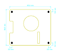
Dimensions
Fig 1 - Mechanical
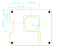
Fig 2 - Connectors
Fig 3 - Fan
Figures 1, 2 and 3 give the different dimensions and the position of the main elements (FAN, connectors, reset button and user led) of the PiSerialPower RPi Hat.
Connectors
Fig 4 - Connectors
The HAT has one USB connector numbered P1, a DC barel Jack connector numbered P3, and two 2.54mm pitch headers numbered P4 (Debug) and P5 (Raspberry Pi connector). Refer to figure 4 for connectors position.
Detailed description of the signals found on each connector pin follow.
P1 is a female USB microB port.
Refer to the Universal Serial Bus (USB) page on Wikipedia for pinout and more information on the USB bus and connectors.
P3 : 2.1mm barrel jack
P3 connector is a standard 2.1mm barrel jack.
+Vin is on the central tip, and GND on the outer sleeve.
Insersion detection is not used.
P3 connector provides access to +Vin and Ground for the onboard step-down regulator. Despite the comment on the schematics, the input ranges from 5V to 24V (28V is the max allowed, and 30V the absolute max the step-down converter can handle) . This lets you power the board using a large variety of power sources.
Note : be very carefull when powering the board with a 24V power-supply, as the voltage can go well above 30V upon power-supply startup and destroy the step-down converter.
Future versions will include a 28V zener diode between Vin and GND to further protect the Hat.
P3 connector
Pin #
Description
RPi signal
RPi Pin
1
+Vin : External unregulated input, +5V to +28V
--
--
2
GND : Ground
GND
GND pins 6, 9, 14, 20, 25, 30, 34 and 39
P4 Connector
P4 connector is a standard 2.54mm (0.1 inch) pitch header, with 1 row of 4 pins.\\
P4 connector provides access to Debug UART and Reset.
P4 connector
Pin #
Description
RPi signal
RPi Pin
1
GND : Ground
GND
GND pins 6, 9, 14, 20, 25, 30, 34 and 39
2
RPi TxD
UART0 Tx
pin 8
3
RPi RxD
UART0 Rx
pin 10
4
5V enable (Reset)
--
--
Note : P4 connector allows direct access to the debug UART and to the power enable pin without powering
the USB-to-UART bridge. This option has been added to allow external access and control of clusters of
Raspberry Pi boards through a single UART concentrator with aditionnal GPIO to control the DC/DC enable
pin.
P5 Connector
P5 connector is a standard 2.54mm (0.1 inch) pitch header, with 2 row of 20 pins.\\
P5 connector provides access to the Raspberry PI expansion header.
P5 connector
Pin #
Description
RPi signal
1
+3.3V from RPi
+3.3V
2
+5V to RPi
+5V
3
SDA : Bidirectional Serial Data for I²C bus 1
I2C1 SDA
4
+5V to RPi
+5V
5
SCL : Clock for I²C bus 1
I2C1 SCL
6
GND : Ground
GND
7
RTC GPIO
GPIO 4
8
RPi TxD
UART0 Tx
9
GND : Ground
GND
10
RPi RxD
UART0 Rx
11
Temp sensor GPIO
GPIO 17
12
RGB Led
GPIO 18 - PWM0
13
--
--
14
GND : Ground
GND
15
--
--
16
--
--
17
+3.3V from RPi
+3.3V
18
--
--
19
--
--
20
GND : Ground
GND
21
--
--
22
--
--
23
--
--
24
--
--
25
GND : Ground
GND
26
--
--
27
SDA : Bidirectional Serial Data for I²C bus 0 (EEPROM)
I2C0 SDA
28
SCL : Clock for I²C bus 0 (EEPROM)
I2C0 SCL
29
--
--
30
GND : Ground
GND
31
--
--
32
--
--
33
Fan PWM
GPIO 13 - PWM1
34
GND : Ground
GND
35
--
--
36
--
--
37
--
--
38
--
--
39
GND : Ground
GND
40
--
--
Electronic components
The PiSerialPower RPi Hat has been created using KiCad EDA software suite for the creation of the schematics and printed circuit boards.
See below for the full schematics. The sources for the schematics are available for download here.
HAT Main Components Description
U1 : TI TPS54302 DC-DC step-down converter.
U2 : FTDI FT230XS USB to UART bridge.
U5 : NXP PCF85363 RTC Clock.
U6 : TI TMP101 I²C temperature sensor.
U7 : ST M24C64 8KB EEPROM
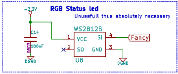
U8 : WS2812B user RGB led.
D1 : Input power Presence.
D2 : Green led : FTDI Rx activity.
D3 : Orange led : FTDI Tx activity.
D4 : USB FTDI Power OK.
D5 : +3.3V Power from RPi.
D6 : +5V to RPi.
D7 : +5V from RPi.
SW1 : Reset button.
J1 : EEPROM write protection jumper (remove for write protection)
USB to UART bridge
In order to ease the development process on Raspberry Pi the HAT provides an USB to UART bridge.
This bridge is made by a FTDI FT230XS chip, which is well supported on most operating systems so there is usually no configuration required to use it as a serial line on the host development system.
It provides a 3.3V regulated voltage for the UART interface but does not power the HAT or the Raspberry Pi.
The FTDI chip controls two "activity" leds for Rx (D2, the green one) and Tx (D3, orange one) data over the serial link.
The USB to UART bridge is connected to UART0 (pins 8 and 10) on the RPi connector. On most variants of the RPi boards this interface must be activated manually in the device tree or in the bootloader configuration on the first partition of the SD card. Refer to the Raspberry Pi User Manual and online documentation and other ressources for more information on how to activate this interface.
I²C
The PiSerialPower RPi Hat uses both I²C busses from the RPi connector.
Bus 0 holds the required EEPROM for HAT identification and configuration, at address 0x50.
Bus 1 holds the TMP101 temperature sensor at address 0x4A and the PCF85363 RTC clock at address 0x51.
The following table shows all the possible I²C Addresses for the I²C components used on the HAT.
I²C Addresses
I²C Component
7 bits I²C address
I²C Address + R / W bit
TMP101 Temperature sensor
0x4A
0x94 / 0x95
PCF85363 RTC Clock
0x51
0xA2 / 0xA3
24C64 EEPROM
0x50
0xA0 / 0xA1
RTC Clock
The HAT includes a PCF85363 RTC with super-capacitor power backup.
The use of a Super-capacitor for power backup lowers the environmental footprint and remove the need to replace (and dispose of) the battery at the expense of a shorter time retention, which is between one and two months, but should be enough for most applications.
The Linux kernel has support for the PCF85363 RTC in the rtc-pcf85363 module.
After loading the rtc-pcf85363 module in the kernel, you must add the RTC to the list of devices on the I²C bus 1 :
This is not necessary if the device tree is loaded from the EEPROM.
You can the access the RTC from /dev/rtc0 or with the hwclock command (from the util-linux package on Debian based GNU/Linux distributions.
Temperature sensor
The HAT has a TMP101 temperature sensor (from Texas Instrument) on the I²C bus 1 (address 0x94 / 0x95).
This temperature sensor has an "alert" function available through a dedicated pin. This pin is routed to pin 11 of the RPI connector (GPIO0_17) which allows the temperature sensor to send an event to the Raspberry Pi.
Refer to the Raspberry Pi User Manual for more information on how to use this signal, and to the TMP101 documentation for more information on the temperature alert signal.
The Linux kernel has support for the TMP101 temperature sensor in the lm75 module.
Once the lm75 module is loaded in the kernel, you must add the TMP101 sensor to the list of devices on the I²C bus 1 :
This is not nessessary if the device tree is loaded from the EEPROM.
You can then read the temperature using the sensors command, which is provided by the lm-sensors package on Debian based GNU/Linux distributions.
EEPROM
In order to respect the Pi HAT design requirements the HAT has a 24C64 (8Kbyte) EEPROM on I²C bus 0 at I²C address 0x50 (7bits).

This EEPROM holds identification data and the HAT device tree blob which is loaded by the Linux kernel to enable the components (RTC and temperature sensor) found on the HAT.

The EEPROM has a write protection pin which must be left floating or driven low to allow write operation. The control of the state of this write protection pin is made by the J1 jumper. When the jumper is present, the pin is driven low and the user can write to the EEPROM.

Removing the jumper disables write operations.
Reset Button
The module has a reset button, connected directly to the enable pin of the step down regulator.

Pressing the button removes power from this power source, which will immediately shut down the Raspberry Pi if it has no other power source, or do nothing if the RPi is also powered from its type C USB connector or any other way.
FAN
The module has a 25mm cooling FAN controlled by pin 33 of the RPI connector (GPIO_13 - PWM1).

This pin is PWM capable, which allows you to control the FAN speed, though the fan used has an internal controller which prevents direct control using PWM, so we added a simple charge pump to modulate the fan voltage, which has the effect of modifing the FAN speed.
Refer to the Raspberry Pi User Manual and online documentation and other resources for more information on how to control the PWM output.
User RGB Led
The module has one WS2812B RGB Led connected to pin 12 of the RPI connector (GPIO_18 - PWM0). This Led is available for the user.

Refer to the Raspberry Pi User Manual and online documentation and other resources for more information on how to control this WS2812B RGB Led.
GPIO support with Raspberry-Pi is a real pain.

Obviously, people do not understand what "stable" means, and try to create new interfaces for GPIO both from the kernel and from the userspace, each supposed to be the very best one, but none usable, making about every piece of information obsolete.