Products/USB UART: Difference between revisions
No edit summary |
|||
| Line 9: | Line 9: | ||
== How-to use == | == How-to use == | ||
== Connectors | == Connectors == | ||
=== P1 Connector === | === P1 Connector === | ||
[[Image:USB_UART_V02_P1.png|300px|right]] | [[Image:USB_UART_V02_P1.png|300px|right]] | ||
P1 connector is a standard 2.54mm (0.1 inch) pitch header, with 2 row of 5 pins.\\ | P1 connector is a standard 2.54mm (0.1 inch) pitch header, with 2 row of 5 pins.\\ | ||
{| class="wikitable" | {| class="wikitable" | ||
!colspan=" | !colspan="4"|P1 connector | ||
|- | |- | ||
| Pin # | | Pin # | ||
| Line 87: | Line 87: | ||
* 24mm x 30mm | * 24mm x 30mm | ||
* Two USB connectors (USB type A male and micro-USB B female) | * Two USB connectors (USB type A male and micro-USB B female) | ||
* Two push buttons for ISP/Reset | |||
* 6 pins on P1 connector (standard 2.54mm (0.1 inch) pitch header, with 2 row of 3 pins). | * 6 pins on P1 connector (standard 2.54mm (0.1 inch) pitch header, with 2 row of 3 pins). | ||
{| class="wikitable" | {| class="wikitable" | ||
!colspan=" | !colspan="4"|P1 connector | ||
|- | |- | ||
| Pin # | | Pin # | ||
| Line 106: | Line 107: | ||
| -- | | -- | ||
|- | |- | ||
|3 | | 3 | ||
| UART Tx | | UART Tx | ||
| TxD | | TxD | ||
| -- | | -- | ||
|- | |- | ||
|4 | | 4 | ||
| UART Rx | | UART Rx | ||
| RxD | | RxD | ||
| -- | | -- | ||
|- | |- | ||
|5 | | 5 | ||
| Reset | | Reset | ||
| RTS | | RTS | ||
| Also connected to SW1 push button | | Also connected to SW1 push button | ||
|- | |- | ||
|6 | | 6 | ||
| ISP | | ISP | ||
| TxDEN | | TxDEN | ||
| Also connected to SW2 push button | | Also connected to SW2 push button | ||
|} | |} | ||
Revision as of 01:19, 25 March 2021

Description
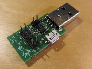
The USB-UART adapter is pretty simple but usefull and ressourcefull. It provides access to a serial link (3.3V UART) from an USB port, either USB male or micro-USB female which is one of the cool special features of this adapter. Another cool feature is the 3.3V and 5V power both available on 2.54mm headers, usefull for most prototyping needs.
This adapter uses an FTDI FT230XS, with most signals available on the UEXT-like connector, and should thus support I2C, SPI, and other protocols or data busses using the bitbanging capabilities of the FTDI chips, though this would require software support on your side as we did not have time to do so yet (We'll keep you up-to-date as soon as we have more information on these).
How-to use
Connectors
P1 Connector
P1 connector is a standard 2.54mm (0.1 inch) pitch header, with 2 row of 5 pins.\\
| P1 connector | |||
|---|---|---|---|
| Pin # | Description | FT230XS signal | Note |
| 1 | +3.3V from FT230XS | +3.3V Out | -- |
| 2 | GND - Ground | -- | -- |
| 3 | UART Tx | TxD | FT230XS pin 1 |
| 4 | UART Rx | RxD | FT230XS pin 4 |
| 5 | I2C SCL | RTS | FT230XS pin 2 |
| 6 | I2C SDA | CTS | FT230XS pin 6 |
| 7 | SPI MISO | Sleep | FT230XS pin 16 |
| 8 | SPI MOSI | TxDEN | FT230XS pin 15 |
| 9 | SPI CLK | RxLed | FT230XS pin 14 |
| 10 | SPI CS | Tx Led | FT230XS pin 7 |
TODO List
- Technical documentation
- I2C and SPI support using the bit-banging capabilities of the FTDI chip (Host side software support)
- SWD and/or JTAG support
- RS232 version
- Low voltage (1.8V) version (microprocessors and SWD/JTAG debug support)
Technical Documentation and Schematics
The technical documentation has not been written yet ...
Version history
V0.1
First version.
- 24mm x 30mm
- Two USB connectors (USB type A male and micro-USB B female)
- Two push buttons for ISP/Reset
- 6 pins on P1 connector (standard 2.54mm (0.1 inch) pitch header, with 2 row of 3 pins).
| P1 connector | |||
|---|---|---|---|
| Pin # | Description | FT230XS signal | Note |
| 1 | +3.3V from FT230XS | +3.3V Out | -- |
| 2 | GND - Ground | -- | -- |
| 3 | UART Tx | TxD | -- |
| 4 | UART Rx | RxD | -- |
| 5 | Reset | RTS | Also connected to SW1 push button |
| 6 | ISP | TxDEN | Also connected to SW2 push button |
