Products/PiSerialPower: Difference between revisions
| Line 39: | Line 39: | ||
The HAT has one USB connector numbered P1, a DC barel Jack connector numbered P3, and two 2.54mm pitch headers numbered P4 (Debug) and P5 (Raspberry Pi connector). Refer to figure 4 for connectors position.<br /> | The HAT has one USB connector numbered P1, a DC barel Jack connector numbered P3, and two 2.54mm pitch headers numbered P4 (Debug) and P5 (Raspberry Pi connector). Refer to figure 4 for connectors position.<br /> | ||
Detailed description of the signals found on each connector pin follow. | Detailed description of the signals found on each connector pin follow. | ||
[[File:Connectors.png|Fig 4 - Connectors]] | [[File:Connectors.png|Fig 4 - Connectors|100px|right]] | ||
=== Electronics === | === Electronics === | ||
Revision as of 00:07, 4 September 2020
Raspberry Pi 4 Hat with 5-28VDC - 3A power with barrel jack input, Fan, RTC with Supercap backup, Debug UART, temp sensor and WS2812 RGB led

Description
The "PiSerialPower" Hat Power-supply Hat for RaspberryPi (and pin-compatible competitors) which also provides a rich set of features :
- 5 to 28VDC barrel jack power input
- 5V - 3A voltage regulator to power the Raspberry Pi
- a Fan (PWM controlled)
- an RTC (PCF85363) with Super capacitor backup (about one month date/time retention, and will not need to be changed in a few years !)
- a USB to UART FTDI chip (FT230XS) to give you access to the debug console using a simple, common micro-USB cable
- a reset button
- a TMP101 temperature sensor
- and a WS2812 RGB led ... well, there was some place left on the PCB ...
The serial and reset signals are also available on a 2.54mm header.
Of course, the board uses the format specified by Raspberry Pi and allows access to both FPC connectors, and is provided with mounting screws.
The board comes fully assembled and tested.
License
- Documentation : Creative Commons CC BY-SA-NC 4.0
- Hardware : The PiSerialPower RPi Hat hardware and schematics are under Creative Commons CC BY-SA-NC 4.0 License. You can produce your own original or modified version of the PiSerialPower RPi Hat, and use it however you like, but not sell them, even without profit.
- Software : All the software examples created by Techno-Innov for the PiSerialPower RPi Hat are under GPLv3 License.
- Note that most of the software you will use with this Hat has not been written by us and is covered by other licenses. Refer to each software for more information.
Hardware
Dimensions
-
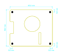
Fig 1 - Mechanical
-
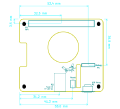
Fig 2 - Connectors
-
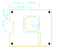
Fig 3 - Fan


Figures 1, 2 and 3 give the different dimensions and the positions of the main elements (FAN, connectors, reset button and user led) of the PiSerialPower RPi Hat.
Connectors
The HAT has one USB connector numbered P1, a DC barel Jack connector numbered P3, and two 2.54mm pitch headers numbered P4 (Debug) and P5 (Raspberry Pi connector). Refer to figure 4 for connectors position.
Detailed description of the signals found on each connector pin follow.

Electronics
The PiSerialPower RPi Hat has been created using KiCad EDA software suite for the creation of the schematics and printed circuit boards.
See below for the full schematics. The sources for the schematics are available for download here.
Software
TODO List
Technical documentation and Schematics
History
v0.1
This board revision has not been sold to public. First prototype version, produced on customer request.
v0.2
Actual version sold as of writting of this documentation. Fixes v01 mistakes and adds PWM for the FAN and a RGB led.